Hydraulic filter
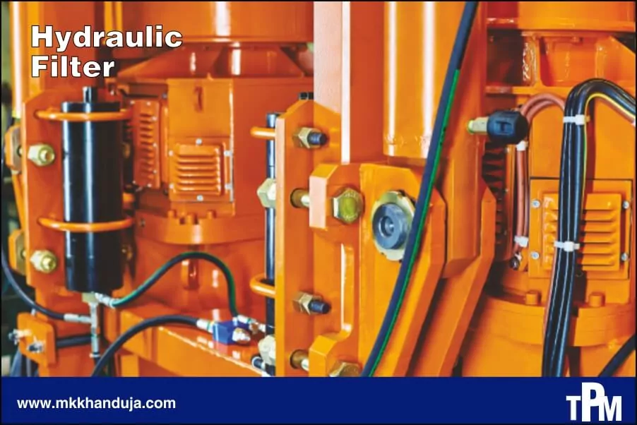
Hydraulic filters protect hydraulic system components from damage due to contamination of oils or other hydraulic fluid in use caused by particles. There are over one million particles larger than 1 micron (0.001 mm or 1 µm) that enters hydraulic system. These particles can cause damage to hydraulic system components because hydraulic oil is easily contaminated. Thus maintaining a good hydraulic filtration system will increase Life of various hydraulic components. The wear of hydraulic system components is dependent on its contamination rate. A hydraulic filter helps to remove particles causing contamination and clean the oil on a continuous basis. The performance of hydraulic filter is measured by its contamination removal rate.
Why hydraulic oil becomes contaminated?
Every hydraulic machine is first manufactured with built-in contamination during machining, cutting, welding and grinding of the reservoir and fixed plumbing. Additionally, contamination ingression also occurs from either new oil (which is dirtier than you imagine) or external sources such as fallout, grime, mud and dust. Finally, the components in system generate their own particles when friction components such as bearings, pistons, spools are rub together.
Removing all forms of particle contamination is the highest priority to ensure a long, reliable life for hydraulic machine. Filters are first line of defense to reduce the number of particles in fluid. Filters also prevent excessive internally-generated contamination, considering particles exacerbate the rate of internally generated contamination, acting like liquid sandpaper.
There are two main types of filter elements, surface and depth.
1. Surface filters
Surface filters are normally constructed from thin sheets of material folded into many sections and then turned into a multi pointed star shape as shown. This allows a large surface area to be used in a small space. The filter fits inside a bowl. They may be in the form of a replaceable cartridge or permanently fitted inside a throw away bowl. The thin sheet s full of pores which trap the solid particles as the fluid passes through them.
Typical materials are
- Cellulose (paper).
- Woven steel fibres.
- Woven nylon fibres.
Paper filter elements are ruined by water which makes them become soggy and the pores close. Another design is the use of a single filament of metal wound into a cylinder.
2. Depth filters
Depth filters are constructed with a thick layer of material with small passages through which the fluid must pass (like a bed of sand for example). The particles become trapped in the passages. The passages may be formed from granules compacted into a thick cylindrical layer or fibres compacted into a tube.
Typical materials are
- Cellulose (paper).
- Synthetic fibres.
- Metal fibres.
- Glass fibres.
- Sintered metal granules.
Contaminants
The main contaminants are
- Welding scale and beads
- Sealing tape shreds
- Shards of screw threads
- Bits of seal material
- Grinding chips
- Wear particles
- Rust
- Water
- Dirt from the atmosphere
- Sludge and varnish from oxides oil
- Biological material such as hair,
- Skin scales, flies and so on.
Solid contaminants get into the clearance spaces between moving parts such as piston and valve spools. They cause wear and damage and may jam the component. Solid particles are removed in the filter by trapping them in tiny passages in the filter element. Particles down to 5 microns (0.005 mm) may be trapped. A typical general purpose filter traps particles of 25 microns.
Water damages paper filters and causes corrosion and lack of lubrication. Water should be removed by settling the fluid in the tank and draining it off. It may also be removed by a centrifuge.
Location
A full flow filter is designed to filter the full output from a pump. It may be placed before the pump (suction filter) or after the pump in which case it must be capable of withstanding the full pressure of the system. It may also be placed in the return line to the tank in which case it does not have to withstand high pressure. Sometimes a separate pump is used solely for the purpose of circulating the fluid through a filter with no great pressure on it. The system in which the fluid may be pumped through a filter at any time independent of the main system is called OFF LINE FILTERING.
The check valve prevents reverse flow and draining of the filter and pump. High precision components such as spool valves are sometimes protected by using a filter adjacent to or part of the component. These would be high quality filters of 5 or 10 microns.
If a filter is not changed when clogged, it is better to allow unfiltered oil through the system than to run with it clogged. In this emergency situation, the oil automatically bypasses the filter element. This may be done with a simple spring loaded valve which is opened by the back pressure. In the diagram of the full flow filter above, the filter element moves against the spring as back pressure builds up and uncovers a bypass hole in the central stem. The symbol below shows a filter with bypass and clogging indicator.
How to protect hydraulic system?
Avoid restrictions which produce a vacuum on the suction side of the pump. If the suction is restricted, air may be drawn in and the oil may form vapour pockets. This will lead to pump damage and oxidation of the oil.
A typical power pack might have on it a thermostat for detecting the fluid temperature. In the event of the fluid overheating, the thermostat might do the following.
- Set off an alarm.
- Switch off the pump
- Switch on a cooling system.
The system might use a separate pump to circulate the oil through a filter and also a cooler. The cooler typically is a heat exchanger with the surrounding air. The thermostat would switch on the cooling fan to boost the cooling rate.
Filters used in the hydraulic system :
Suction line filter: A filter which is located between reservoir and pump
Return line filter: A filter which is located on the return line, just before the line enters the reservoir
Key points :
Pump must be protected against cavitation
Risk of cavitation , particularly at low temperature.
Fine filtration not possible
Return line filters :
Return line filter are located in the return line as an inline filter or as a tank-mounted filter on the tank or in the tank. This means that the operating fluid coming from the system flows back into the tank completely filtered .Therefore all contaminated particles are filtered from the fluid before reaching the tank. When selecting the correct filter size, and the maximum possible flow rate must be taken into account. To avoid possible foaming of the fluid in the tank, the fluid outlet from the filter is always below the fluid level in all operating conditions.
Benefits :
- No System contamination reaches the tank
- All fluid flowing back to the tank.
Key points :
In case of high- value components a pressure filter must be used in addition
In case of single filters, the system must be switched off to change the element.
Large filters are required for high flow rates
It is advisable to fit a bypass valve
Advantage of suction and return line filters :
According to filtration view, the pump intake is an ideal location for filtering media. The absence of both high fluid velocity, which disturbs trapped particles, and high pressure – drop across the element, which can cause migration of particles through the media, increase filter efficiency. These advantages are outweighed by the restriction the element creates in the intake line and the negative effect this has on the pump life.
The principal for locating filtering media in the return line is : If the reservoir and the fluid it contains starts out clean and all air entering the reservoir and returning fluid is adequately filtered, then fluid cleanliness will be maintained. The other advantage of the return line as the filter location with that sufficient pressure is available to force the fluid through fine media (typically 10 microns),but the pressure is not high enough to alter filter or housing design. This combined with
relatively low flow velocity, means that a high degree of filtering efficiency can be achieved at an economical cost. For these reasons return line filtration is a feature of most hydraulic systems. The main disadvantage of return line filtration is that the back pressure created by the element can damage some components.
Comments