Electrical Distribution System
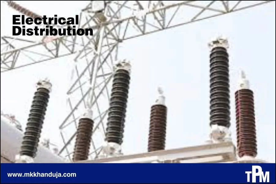
Electrical distribution system is an essential part of industrial electrical power supply. It just transfers power from source to where it is utilized through various protective devices, transformers and other devices that are covered in following sections.
Electrical distribution system is the most critical part of industry; any breakdown in this system may lead to complete halt. So, it’s a part which needs utmost care and proper timely maintenance for Electrical distribution system is an essential part of industrial electrical power supply. It just transfers power from source to where it is utilized through various protective devices, transformers and other devices that are covered in following sections.
Electrical distribution system is the most critical part of industry; any breakdown in this system may lead to complete halt. So, it’s a part which needs utmost care and proper timely maintenance for proper functioning of industry but it is often ignored that leads in extra repairing cost, Production loss and poorly maintained electrical distribution system consume about 50% more electricity than a well-maintained electrical distribution system. Some of the losses are from transformer losses, low power factor, cables/wires losses, heat losses etc. None of these losses can be eliminated completely but can be minimized by proper techniques, Proper maintenance and timely maintenance.
In the next sections every device and equipment of electrical distribution system is covered. So, for the ease of understanding electrical distribution system is covered in two parts:
1. 11kv/33kv line to LT/HT panel
2. LT/HT panel to the machines/appliances
11kv/33kv line to LT/HT panel:
components from the line from power grid to LT/HT panel it comprises of Lightning arrester, Circuit breaker, isolator, transformer etc etc. All these devices are really critical for the safety and breakdown in any one these will lead in huge loss.
1. lightning arrester
A lightning arrester is also known as surge arrester. It’s a switching or diverting device which in case of lightning it diverts the excessive current to the ground. The typical lightning arrester has a high voltage terminal and a ground terminal. When a lightning surge travels along the power line to arrester, the current from surge is diverted through the arrester, to the earth and protects the other electrical instruments.
2. Circuit breaker
It’s an equipment which automatically cuts off the power supply in case of any fault or short circuit. The most commonly used circuit breaker in industries are:
a. Vacuum circuit breaker
b. Air circuit breaker
c. Molded case circuit breaker
d. Miniature circuit breaker
A. Vacuum circuit breaker:
This type of circuit breaker is used for voltage rating 11kv to 33kv. In this circuit breaker, the fixed and moving contact is enclosed in a permanently sealed vacuum interrupter. The arc is extinct as the contacts are separated in high vacuum. Vacuum circuit breaker has a high insulating medium for arc extinction as compared to the other circuit breaker.
B. Air circuit breaker:
In air break circuit breaker the arc is initiated and extinguish in substantially static air in which the arc moves. Such breakers are used for low voltages,
generally up to 11KV and rupturing capacities of 500MVA.
C. Molded case circuit breaker:
This type of circuit breaker is Used for 230V or 440V. Rated current up to 1600A. Molded case circuit breakers have very high current ratings, which allows them to be used in heavy duty applications. Some applications
include main electric feeder panel, capacitor bank protection, generator protection, welding machine protection etc.
D. Miniature circuit breaker:
It is Used for 230V or 440V and rated current not more than 125amp. Generally used for particular machines or Group of small equipment.
3. Isolator
Isolator is a device used to isolate all equipment from the source of power. It is complete mechanical or manually operated device. It is employed on both ends of the circuit breaker. It is generally operated only at the time of maintenance. Make sure it should be operated at no-load condition.
4. Instrument transformer
Instrument Transformers are basically used to operate instruments or metering from high voltage or high current circuits, safely isolating secondary control circuitry from the high voltages or currents Types of instrument transformer:
1. Current Transformer (CT)
Current transformers are generally used to measure currents of high magnitude. These transformers step down the current to be measured, so that it can be measured with a normal range ammeter.
2. Potential transformer (PT)
Potential transformers are also known as voltage transformers and they are basically step-down transformers with extremely accurate turns ratio. Potential transformers step down the voltage of high magnitude to a lower voltage which can be measured with standard measuring instrument.
No. of turns in both CT and PT are decided by the formula:
Turns ratio= Np/Ns = Vp/Vs = Is/Ip
Where,
Np: No. of turns in primary windings
Ns: No. of turns in secondary windings
Vp: Voltage in primary windings
Vs: Voltage in secondary windings
Is: Current in secondary windings
Ip: Current in primary windings
5. Distribution transformer
It is electrical device which steps down the primary voltage of 33kv/11kv to secondary distribution voltage of 415-440 volts between phases and 215 volts between phase and neutral through delta star windings by electromagnetic
induction without change in frequency.
Delta star windings
Though we have lot of different windings connection for transformer but the most suited for the industries are the delta star windings due to its unignorable advantages over other windings. Some of its advantages are stated below:
a. It can be used as three phase four wire system due to
availability of neutral at secondary output.
b. No distortion in secondary windings.
c. It can handle large unbalanced load.
d. Grounding isolation between primary and secondary windings
6. Diesel Generator
1. Engine: This is typical a bigger diesel engine with 6 or 8 heads that consume diesel and converts it into mechanical power.
2. Alternator: This is the part that turns the mechanical energy (the rotation of the shaft) into electrical power through induction.
3. Voltage regulator: This is a fairly complex but important component. Without it, the voltage and amperage of the AC current provided would vary according to the speed of the engine.
The other supporting system which are essential for proper functioning of DGs are:
1. Fuel system
2. Cooling system
3. Exhaust system
4. Lubrication system
5. Starter and battery system
How efficient is a diesel generator?
The efficiency of a well-maintained DG set is only 35% means only 35% of chemical energy converts into electrical energy. But its so user friendly that we are paying Rs 20/- for 1kwh energy. This amount may go up to Rs 40/- for a poorly maintained DG set. There are lot of ways to increase the efficiency of DG through maintenance and some installation guidelines some of them are listed below:
1. In the DG set the Higher back pressure at exhaust leads to Lower fuel economy, and so to keep the exhaust piping to be minimum.
2. DG Set building should be Positive cross ventilated. Increase in air intake temperature from 25°C to 40°C, the air fuel ratio decreases by about 5%; that is diesel losses happen by 1 % for every 4 *C rise above the outside ambient temperature.
3. A poorly maintained fuel injection pump increases fuel consumption by 4 gm/kWh i.e. Correction gives 2 % savings.
4. Blocked fuel filters increase fuel consumption by 2gm/kWh i.e. Correction gives 1 % savings.
LT/HT panel to machines/appliances
In this line power transfer take place through Lt panel/Ht panel to other sub panels that consists no of MCBs voltammeter, ammeter and then to the machine via switch.
1. LT panel
LT Panels are used with low tension cables to obtain power from the generator or transformer and distribute electricity to various electrical devices and distribution boards.LT panels are designed to function at lower voltage
of around 450V.
Metering and indication of factors like voltage, amperage and power factor is displayed in LT panel. On all LT panels, indicating lamps are provided for each phase for indicating live or fault condition. Start and stop push buttons also provided on metering panel to give input commands such as turn ON supply and emergency stop. Example of LT panel connection containing incomer from
transformer only:
Main parts of LT panel:
a. Change over switch
b. Bus bar
c. APFC panel
A. change over switch:
Electricity from the commercial power grid to a local generator or vice versa according to supply from power grid. This can be done
B. Bus bar:
An electrical bus bar is defined as a conductor or a group of conductors used for collecting electric power from the incoming feeders and distributes them to the outgoing feeders.
C. APFC panel
APFC panel consists of multiple capacitors of different ratings whose switching can be controlled as per requirement. An APFC is effective as a single-point
installation which can be used to control the power factor for a large number of loads, instead of installing capacitors at the individual locations of each load.
Cause of low power factor
The inductive load. The current in the inductive load lag behind the voltage. The power factor is therefore lagging. The important inductive loads responsible for the low power factor are the three-phase induction motors (which operate at a 0.8 lagging power factor), transformer, lamps and welding equipment operate at low lagging power factors.
Lower the power factor higher the amount needs to pay its like you are taking power from grid but can’t utilize most of it but you need to pay for that lost power. More the power you lost more is the amount you have to pay and also the fine imposed by the power grid.
2. Servo stabilizer
A Servo Stabilizer is a Servo motor-controlled stabilization system that performs optimum voltage supply using a Buck\Boost transformer booster that captures voltage fluctuations from input and regulates current to the correct output. An AC synchronous motor adjusts voltage in clockwise or anticlockwise direction and manages the output voltage with components like control card, dimmer, comparator, transistors etc.
3. Sub distribution board
These distribution board consists of various MCBs and MCCBs for different machines or group of machines
depending upon the load. It can also be used as a switch and protective device. Each sub distribution board consists of ammeter and voltmeter for power measurement.
From the article above it is very much clear about the devices in electrical distribution system, its significance in the system and its negative effect if not properly maintained. What are the possible ways to improve electrical distribution system, sources of loss in power and ways to reduce power losses.
Electrical distribution system is the most critical part of industry; any breakdown in this system may lead to complete halt. So, it’s a part which needs utmost care and proper timely maintenance for proper functioning of industry but it is often ignored that leads in extra repairing cost, Production loss and poorly maintained electrical distribution system consume about 50% more electricity than a well-maintained electrical distribution system. Some of the losses are from transformer losses, low power factor, cables/wires losses, heat losses etc. None of these losses can be eliminated completely but can be minimized by proper techniques, Proper maintenance and timely maintenance.
In the next sections every device and equipment of electrical distribution system is covered. So, for the ease of understanding electrical distribution system is covered in two parts:
1. 11kv/33kv line to LT/HT panel
2. LT/HT panel to the machines/appliances
11kv/33kv line to LT/HT panel:
components from the line from power grid to LT/HT panel it comprises of Lightning arrester, Circuit breaker, isolator, transformer etc etc. All these devices are really critical for the safety and breakdown in any one these will lead in huge loss.
1. lightning arrester
A lightning arrester is also known as surge arrester. It’s a switching or diverting device which in case of lightning it diverts the excessive current to the ground. The typical lightning arrester has a high voltage terminal and a ground terminal. When a lightning surge travels along the power line to arrester, the current from surge is diverted through the arrester, to the earth and protects the other electrical instruments.
2. Circuit breaker
It’s an equipment which automatically cuts off the power supply in case of any fault or short circuit. The most commonly used circuit breaker in industries are:
a. Vacuum circuit breaker
b. Air circuit breaker
c. Molded case circuit breaker
d. Miniature circuit breaker
A. Vacuum circuit breaker:
This type of circuit breaker is used for voltage rating 11kv to 33kv. In this circuit breaker, the fixed and moving contact is enclosed in a permanently sealed vacuum interrupter. The arc is extinct as the contacts are separated in high vacuum. Vacuum circuit breaker has a high insulating medium for arc extinction as compared to the other circuit breaker.
B. Air circuit breaker:
In air break circuit breaker the arc is initiated and extinguish in substantially static air in which the arc moves. Such breakers are used for low voltages,
generally up to 11KV and rupturing capacities of 500MVA.
C. Molded case circuit breaker:
This type of circuit breaker is Used for 230V or 440V. Rated current up to 1600A. Molded case circuit breakers have very high current ratings, which allows them to be used in heavy duty applications. Some applications
include main electric feeder panel, capacitor bank protection, generator protection, welding machine protection etc.
D. Miniature circuit breaker:
It is Used for 230V or 440V and rated current not more than 125amp. Generally used for particular machines or Group of small equipment.
3. Isolator
Isolator is a device used to isolate all equipment from the source of power. It is complete mechanical or manually operated device. It is employed on both ends of the circuit breaker. It is generally operated only at the time of maintenance. Make sure it should be operated at no-load condition.
4. Instrument transformer
Instrument Transformers are basically used to operate instruments or metering from high voltage or high current circuits, safely isolating secondary control circuitry from the high voltages or currents Types of instrument transformer:
1. Current Transformer (CT)
Current transformers are generally used to measure currents of high magnitude. These transformers step down the current to be measured, so that it can be measured with a normal range ammeter.
2. Potential transformer (PT)
Potential transformers are also known as voltage transformers and they are basically step-down transformers with extremely accurate turns ratio. Potential transformers step down the voltage of high magnitude to a lower voltage which can be measured with standard measuring instrument.
No. of turns in both CT and PT are decided by the formula:
Turns ratio= Np/Ns = Vp/Vs = Is/Ip
Where,
Np: No. of turns in primary windings
Ns: No. of turns in secondary windings
Vp: Voltage in primary windings
Vs: Voltage in secondary windings
Is: Current in secondary windings
Ip: Current in primary windings
5. Distribution transformer
It is electrical device which steps down the primary voltage of 33kv/11kv to secondary distribution voltage of 415-440 volts between phases and 215 volts between phase and neutral through delta star windings by electromagnetic
induction without change in frequency.
Delta star windings
Though we have lot of different windings connection for transformer but the most suited for the industries are the delta star windings due to its unignorable advantages over other windings. Some of its advantages are stated below:
a. It can be used as three phase four wire system due to
availability of neutral at secondary output.
b. No distortion in secondary windings.
c. It can handle large unbalanced load.
d. Grounding isolation between primary and secondary windings
- Fluid level gauge
- Buchholz relay
- Vacuum gauge
- Bushings
- Pressure vacuum switch
- Tap changer
- Sudden pressure relay
- Marshalling kiosk
- Pressure relief valve
- Cooling system
- Fluid temperature indicator
- Hot spot temperature indicator
- Neutral grounding arrester
6. Diesel Generator
1. Engine: This is typical a bigger diesel engine with 6 or 8 heads that consume diesel and converts it into mechanical power.
2. Alternator: This is the part that turns the mechanical energy (the rotation of the shaft) into electrical power through induction.
3. Voltage regulator: This is a fairly complex but important component. Without it, the voltage and amperage of the AC current provided would vary according to the speed of the engine.
The other supporting system which are essential for proper functioning of DGs are:
1. Fuel system
2. Cooling system
3. Exhaust system
4. Lubrication system
5. Starter and battery system
How efficient is a diesel generator?
The efficiency of a well-maintained DG set is only 35% means only 35% of chemical energy converts into electrical energy. But its so user friendly that we are paying Rs 20/- for 1kwh energy. This amount may go up to Rs 40/- for a poorly maintained DG set. There are lot of ways to increase the efficiency of DG through maintenance and some installation guidelines some of them are listed below:
1. In the DG set the Higher back pressure at exhaust leads to Lower fuel economy, and so to keep the exhaust piping to be minimum.
2. DG Set building should be Positive cross ventilated. Increase in air intake temperature from 25°C to 40°C, the air fuel ratio decreases by about 5%; that is diesel losses happen by 1 % for every 4 *C rise above the outside ambient temperature.
3. A poorly maintained fuel injection pump increases fuel consumption by 4 gm/kWh i.e. Correction gives 2 % savings.
4. Blocked fuel filters increase fuel consumption by 2gm/kWh i.e. Correction gives 1 % savings.
LT/HT panel to machines/appliances
In this line power transfer take place through Lt panel/Ht panel to other sub panels that consists no of MCBs voltammeter, ammeter and then to the machine via switch.
1. LT panel
LT Panels are used with low tension cables to obtain power from the generator or transformer and distribute electricity to various electrical devices and distribution boards.LT panels are designed to function at lower voltage
of around 450V.
Metering and indication of factors like voltage, amperage and power factor is displayed in LT panel. On all LT panels, indicating lamps are provided for each phase for indicating live or fault condition. Start and stop push buttons also provided on metering panel to give input commands such as turn ON supply and emergency stop. Example of LT panel connection containing incomer from
transformer only:
Main parts of LT panel:
a. Change over switch
b. Bus bar
c. APFC panel
A. change over switch:
Electricity from the commercial power grid to a local generator or vice versa according to supply from power grid. This can be done
B. Bus bar:
An electrical bus bar is defined as a conductor or a group of conductors used for collecting electric power from the incoming feeders and distributes them to the outgoing feeders.
C. APFC panel
APFC panel consists of multiple capacitors of different ratings whose switching can be controlled as per requirement. An APFC is effective as a single-point
installation which can be used to control the power factor for a large number of loads, instead of installing capacitors at the individual locations of each load.
Cause of low power factor
The inductive load. The current in the inductive load lag behind the voltage. The power factor is therefore lagging. The important inductive loads responsible for the low power factor are the three-phase induction motors (which operate at a 0.8 lagging power factor), transformer, lamps and welding equipment operate at low lagging power factors.
Lower the power factor higher the amount needs to pay its like you are taking power from grid but can’t utilize most of it but you need to pay for that lost power. More the power you lost more is the amount you have to pay and also the fine imposed by the power grid.
2. Servo stabilizer
A Servo Stabilizer is a Servo motor-controlled stabilization system that performs optimum voltage supply using a Buck\Boost transformer booster that captures voltage fluctuations from input and regulates current to the correct output. An AC synchronous motor adjusts voltage in clockwise or anticlockwise direction and manages the output voltage with components like control card, dimmer, comparator, transistors etc.
3. Sub distribution board
These distribution board consists of various MCBs and MCCBs for different machines or group of machines
depending upon the load. It can also be used as a switch and protective device. Each sub distribution board consists of ammeter and voltmeter for power measurement.
From the article above it is very much clear about the devices in electrical distribution system, its significance in the system and its negative effect if not properly maintained. What are the possible ways to improve electrical distribution system, sources of loss in power and ways to reduce power losses.
Comments